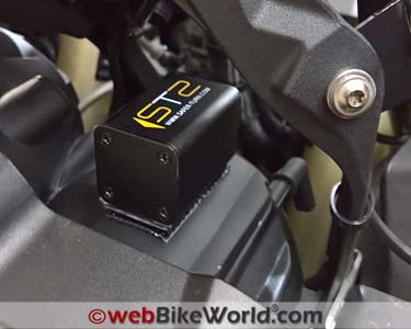
A Smart Turn Signal Cancelling System for Motorcycles
Summary
Turn signal use is a critical requirement at any time, and once turned on, they need to be turned off in a timely manner.
Failure to do so can cause confusion for both oncoming and following traffic, leading to serious consequences.
And this is where the Smart Turn System comes into play.
The Smart Turn System or STS is an automatic turn signal cancellation system designed specifically for motorcycles.
It uses a microprocessor to monitor 300 different data elements per second to determine what the motorcycle is doing.
Data such as acceleration, inclination, heading and vibration of the motorcycle is all used to process the output.
The STS then provides an accurate, correct and timely cancellation of an activated turn signal with little intervention required by the rider beyond initiating the turn signal switch prior to the turn.
The system then provides the appropriate output response to the turn signals at just the right time.
There are one or two caveats.
For example, the system can be foiled with an extremely short or slight change in position or repeated rapid turns or transitions through certain types of traffic circles (roundabouts), although these are rare exceptions and certainly not the rule.
But there’s a built-in fail-safe that provides a 14-second counter that automatically cancels the active signal, again with normal progression.
Of course, the rider can always cancel the turn signal manually at any time.
Small, rugged and waterproof, the STS is relatively simple to install and once a short set-up test is conducted, it’s ready for use.
Function and performance of the Smart Turn System or STS is hard to fault under virtually any riding environment and a wide range of traffic conditions.
The Slovenian-based company offers a 100 percent money back guarantee and a one year warranty.
Overview
There are more than a few phrases and expressions we’ve all seen regarding vehicle use with one of the most common being the slogan, “Share the Road”.
Admittedly a phrase such as this obviously means different things to different road users, however.
In wanting to survive each and every riding experience and come away with positive thoughts, we need knowledge, understanding, experience, situational awareness and communication skills to maintain our individual and shared safety envelopes.
The other critical ingredient is our motorcycle, with its own features and capabilities.
Modern motorcycles are equipped or adorned with any number of passive and active safety systems, all of which can and should make motorcycling more enjoyable and safe.
But not of all these systems work seamlessly in the background. Some of them (still) need rider intervention — like turn signal activation and cancelling.
Turn signals provide timely, dynamic, active and hopefully accurate communications between road users. Failure to use them can lead to a potentially dangerous or escalating traffic situation.
My point here? Turn signals need to be used; i.e., activated in a timely manner and by the same token deactivated in a timely manner. It’s a two-step process, both ON and OFF.
It’s bad enough when a rider is so lazy that they won’t use a turn signal and just as bad or worse, depending on where you are in traffic when that turn signal isn’t cancelled in a timely manner.
The consequences of incorrect use of turn signals cannot be ignored; a fact borne out by a lot of statistics.
One only needs to do an online search to find lots (and lots) of validated reference material.
Many of us ride motorcycles that have crude electronic or self-cancelling turn signals, the function of which is typically based on a default time or calculated distance travelled based on speed.
Some turn signal systems are even more sophisticated in being able to assess other conditions, including lean angle, to determine the appropriate time to cancel.
And even if you trust a self-cancelling system implicitly, remaining a creature of habit and making sure they are turned off at the appropriate time could save your life or the life or lives of other road users.
The Smart Turn System or STS brings a technology-based solution that can add a little more assurance to the turn signal equation, providing a bit of added safety to your ride.
Overview
The Smart Turn System or STS is a relatively new product from a Slovenian start-up company, ABCS SISTEM Ltd.
The development team of electrical and mechanical engineers are also riding enthusiasts with a penchant for staying safe and their assessment, analysis and R&D lead to the development of the STS.
The STS is basically a “black box” containing a microprocessor and system that is plumbed or spliced into the motorcycle’s turn signal wiring.
It measures acceleration, inclination, heading and vibration — up to 300 different data elements per second, according to the company.
The measurements determine what the motorcycle is doing under rider control so to provide the appropriate system output response at the right time.
The STS detects, recognizes and differentiates between left and right turns, lane changes, roundabout (traffic circle) movements and over-taking.
Its functionality is simple; with the turn signal activated by the rider, once the maneuver (lane change, turn, traffic-circle or whatever) is completed the STS cancels the turn signal automatically.
Some very quick or slight maneuvers may not be detected, in which case the STS may not immediately cancel an activated turn signal.
But the STS has a fail-safe mode that will turn off the activated turn signal after 14 seconds of movement unless cancelled earlier by the rider.
The simple boxed package contains the STS unit, five connectors, zip ties and small foam pieces (used for the mechanical version) and an installation manual.
In addition to the printed instructions, all version instructions in short and long form as well as additional information is available online with some interesting background and research facts.
The Smart Turn System (STS) device and its methods are patented and the product is certified for road use and carries FCC, e26, CE and German TUV compliance certifications.
STS Versions
To allow installation on a wide variety of motorcycles, both old and new, two versions of the STS are offered: mechanical and electronic.
The electronic version was used for this review and we installed it on a 2014 BMW F 800 GSA.
Here’s a quick check to help you determine which version is required for your motorcycle: with the ignition/engine off, activate a turn signal, then start the motorcycle. If the turn signal is blinking, it is a mechanical switch.
For reference purposes, newer motorcycles — especially those from Aprilia, BMW, Ducati or those with a form of CAN bus — require the electronic version.
But do the check regardless or contact STS for more information.
STS Size, Shape & Layout
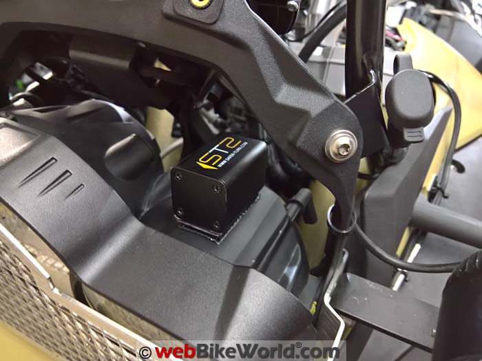
The STS “black box” measures 32 mm by 32 mm by 45 mm (1.25 x 1.25 x 1.77 inches). It’s a sealed module with the STS logo on top and an orientation arrow pointing forward.
A sturdy weatherproof 50 cm (20 inch) long harness exits from the rear of the module.
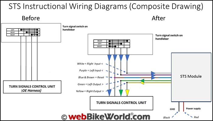
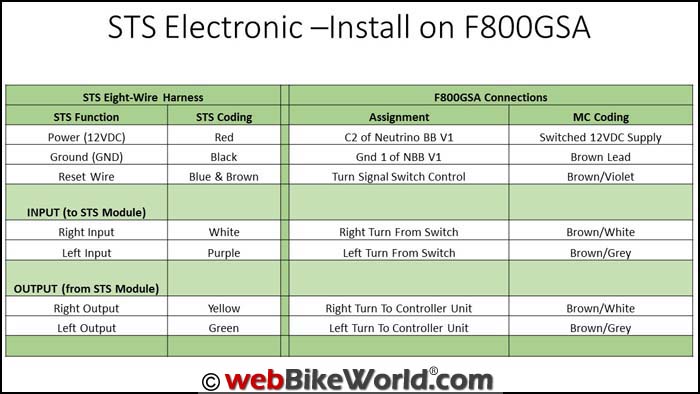
Housed inside the sheathing are 8 wires terminated with spade (Faston) connectors (Note: with the electronic version, the two switch or reset leads are mated into one for a total of seven connections.)
Following is the Wiring Harness Function by Grouping Color:
- Red: 12VDC switched power supply.
- Black: System ground.
- White: Right turn signal INPUT (from handlebar switch to STS).
- Purple: Left turn signal INPUT (from handlebar switch to STS).
- Blue/Brown: Reset (common between handlebar switch and controller).
- Yellow: Right turn signal OUTPUT (from STS to controller).
- Green: Left turn signal OUTPUT (from STS to controller).
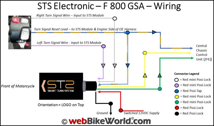
The STS module, like many other aftermarket systems, is installed as an “in-line” component to interface directly with existing on-board controls, without negatively impacting any on-board operations, of course.
As such, the STS needs to interface with both the turn signal controls of the left handlebar nacelle and the central chassis control unit or ZFE so that onboard continuity is provided as well as the enhanced functionality added by the STS system.
STS Installation
The current documentation for STS installation is fairly generic, consisting of basic instructions and connection tables, which provide the essentials.
You will have to know the wiring diagram for your motorcycle’s turn signal system, however.
The various tables and visuals in the instructions are identified as “illustrative”, with generic (not specific) motorcycle instructions provided, although that might change as the product evolves.
The most important thing to understand are the Input, Output and Reset functions and how they interface with the host motorcycle.
You’ll need to understand which turn signal wires on your motorcycle need to be accessed and how you can gain access to them.
Then you’ll have to determine the best way to access, cut and splice the wires into the STS, keeping in mind STS wiring harness length and its multiple connections.
The installation is motorcycle-specific, so locating and accessing the necessary turn signal wires in the bike’s wiring harness may be either relatively straightforward, while on other bikes it can be very difficult.
Again, insight into your motorcycle’s wiring harness and some finicky finger work may be needed…but you’ll have to trust us, the results are worth it.
LIN Bus Exclusions
With STS documentation clearly identifying that LIN bus equipped (multi-function-controller) Beemers aren’t compatible hosts, the two BMW R 1200 GSW machines in the home fleet were excluded from the short list.
Enter the somewhat smaller, lighter and nimbler little BMW F 800 GSA, also known as the F 800 GS Adventure.
It doesn’t seem to be a common host for the electronic version of the STS, which is exactly why it seemed perfect for this review.
Thankfully, unlike one documented step shown for the mechanical version, direct access to the multi-function and expensive sealed nacelle on the bike isn’t needed to get the electronic version of the STS up and running.
What is needed on this bike however, is access to the primary wiring harness and three of its bundled wires that control the turn signals, along with a stable horizontal mounting spot for the STS control module.
Positioning the STS Control Module
Locating the ideal position for securing the actual STS “black box” module can be done before or after the wiring connections are completed.
It will all depend on your motorcycle, the location of the turn signal wiring harness and of course, access to the wires.
Note, however, that the instructions call for the STS box to be mounted close to horizontal, with the logo oriented on top and the direction arrow facing forward on the bike.
The STS wiring harness is then located at the back of the module, in close proximity to where the wire connections from the bike’s turn signals will be made.
Mounting locations for the module will vary for each bike.
On the 2014 F 800 GSA, I used a small rectangular section of 3M Dual-Lock to hold the STS module firmly in place on the plastic of the headlight shell.
The Motorcycle’s Wiring Harness
Again, wiring will be different, depending on your motorcycle. But for illustrative purposes, we’ll describe the installation of the STS on a BMW F 800 GSA.
The STS wiring harness runs down between the left side bulb access cover and the sub-frame bracket.
It then turns back up towards where the main harness of the left handlebar nacelle sits, keeping everything close together.
The left handlebar nacelle main harness on the bike is continuous; it exits the housing, runs in front of the handlebar to the centre, then down on the left side of the steering head and back to the Central Chassis Control Unit (ZFE) module located behind the steering head.
Best access to the harness is the area between where the harness turns down through the wire guide and a section of hard plastic tubing starts (used for frame/heat shielding).
I removed the wire guide and worked the main harness out of it as doing so facilitates access to and easier handling of the harness. Once done, the wire guide can be reinstalled.
The outer harness sheath can be cut and peeled back about 13 cm (~5.0 inches), exposing the bundle of 16 thin wires on the BMW.
Careful separation of the wires allows the necessary sleuthing to find the needed three connections for the bike’s turn signals.
I know most of the wire color code assignments for this bike, since I’ve completed various other electrical installations on other F-series motorcycles.
But I still reference the information provided by the Haynes Online Manual for BMW F 650/700/800 Twins (2006 to 2016).
(An aside, a one-year subscription is $29.99 USD and it pays for itself in very short order and is slightly less expensive than the admittedly more-detailed DVD-based BMW Repair Manual typically listing for 70.00 to 100 USD.)
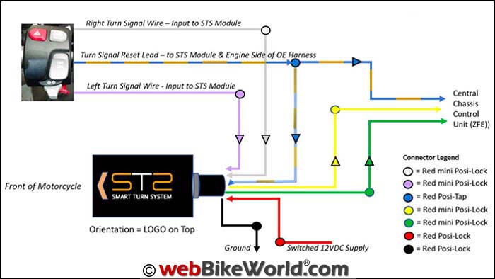
With the Left (Brown/Grey), Right (Brown/White) and Reset (Brown/Violet) wires identified, the three wires are temporarily tagged for work purposes.
Note that these wire colour-codes are for the F 800 GSA and are not representative of any or all motorcycles.
Notes on the Mechanical vs. Electronic Versions
The primary difference between the mechanical and electronic variants of the STS is in how the reset or switch function interface is made.
Where the mechanical variant requires three (left, right and reset) connections on the Input (handlebar switch side) and three on the Output (control unit side), the electronic interface combines the reset input/output (Blue & Brown) wires.
Some of the STS photos and diagrams show a mix of round and flat connectors.
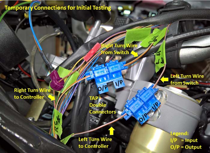
But the electronic version product we received used flat terminal spade or Faston connectors for the leads, and single or double Tap connector pieces for the in-line connections.
Wiring in the STS is relatively straightforward, but again, make sure the Input and Output sides of the left and right signal light leads are installed correctly. Both wires can be cut at the same time or individually based on the desired order of work.
Note also that the reset wire does not need to be cut when installing the electronic version.
The supplied Blue taps have two separate molded sections to provide the electrical separation between the cut ends of each turn signal wire with each section housing its own metal contact insert to make the connection between the wire and the appropriate STS spade connector.
Step-by-Step Connectivity and Testing
Again, note that the INPUT = handlebar switch to STS; OUTPUT = from STS to control unit.
Cut the left and right signal light wires (if desired for reference purposes mark them at INPUT (switch side) and OUTPUT (control unit side).
With one of the Blue Tap connectors, insert the switch side of the Right turn wire into one side of the connector and then the control side of the Right turn wire into the other side of the connector (wires will sit inside the small pass-through cradles).
With the leads aligned in their pass-through cradles, push each cap section that houses the contact insert into place, forcing the lead to engage with the insert to cut the insulation and make the wire contact.
Use a small set of pliers if needed to fully close and ‘snap’ the caps into place.
Repeat the above steps for the Left turn wire sections.
If desired, mark Left and Right connectors and INPUT/OUTPUT sides.
With one of the Violet Tap pieces, make an in-line connection to the identified Reset wire from the switch (this lead DOES NOT NEED to be cut when installing the electronic version).
Take the remaining two Violet Tap pieces and make in-line (or direct) connections between the Red STS wire to a 12VDC switched power source and the Black STS wire to a chassis or harness ground (see more installation options below).
Insert the combined Blue & Brown connector into the Reset wire’s Tap connector.
Insert the Yellow STS connector into the Right turn OUTPUT half of the dual connector.
Insert the Green STS connector into the Left turn OUTPUT half of the dual connector.
Check all connections made to this point.
Initial Check
Turn the ignition on, making sure the power source for the STS is active.
To finish connecting the system, insert the White STS connector into the Right turn signal INPUT slot of the dual connector, then insert the Purple STS connector into the Left turn signal INPUT slot of the dual connector.
The turn signals (should) present a very fast left and right blink, confirming that all is good so far. Turn the ignition off. If no output, recheck the connections/power/ground.
Insert the White STS connector into the Right turn signal INPUT slot of the dual connector, then insert the Purple STS connector into the Left turn signal INPUT slot of the dual connector.
System Test
With the motorcycle on the centre stand or with a rider supporting the motorcycle, turn on the ignition, start the motorcycle and wait a few seconds.
Activate the left indicator and wait 30 seconds then cancel. Repeat the sequence for the right turn signal, then turn ignition off.
Conduct a check of all work done, reinstall removed components and go for a test ride.
Installation Options
Once the essential installation requirements are sorted out regarding STS module placement and routing of the harness and connectivity, some options become apparent depending on the motorcycle and of course the user’s experience.
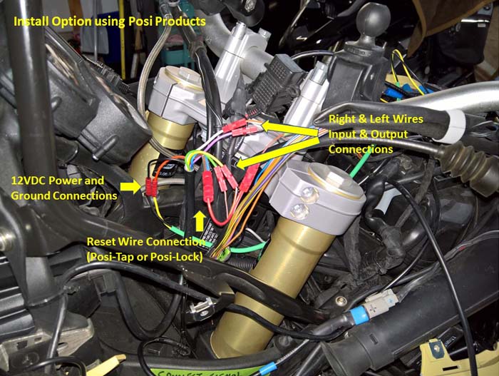
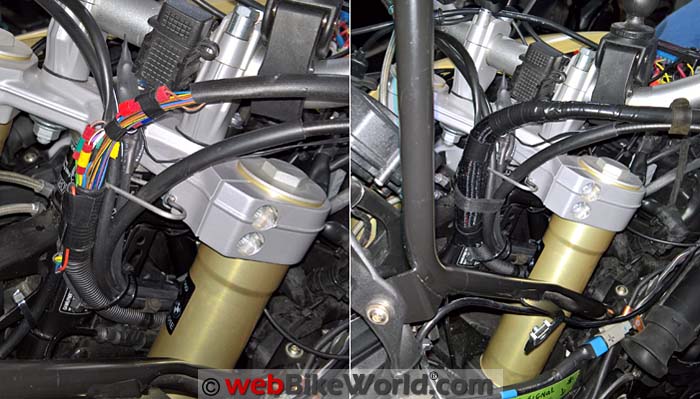
For my part in being somewhat adverse to the (slightly) harder to use and bulkier tap-style connectors, I elected to use (surprise, surprise) individual Posi-Taps and Posi-Locks to make the needed connections.
After cutting the spade connectors off from the leads and trimming the ends back 10-12 mm (~0.25 inches) for Posi use, the solution I used is this:
Four mini red Posi-Locks for the Left and Right Input and Output connections to the respective colour-coded STS wires.
One Red or Blue Posi-Tap for the Blue & Brown combination tapped into the reset wire.
Two regular (or mini) Red Posi-Locks for power and ground connections (using a Neutrino BB V2 (review) circuit for this installation).
With STS harness leads positioned parallel to the needed wires from the handlebar harness, making the Posi-connections is simpler than using the Tap connectors and much lower profile.
I also placed all wiring and connections inside a length of 0.75 inch Flexo F6.
If or when the STS is removed, it will be a simple matter to unwrap and access the connections to separate the respective wires.
You can then restore the original layout by reusing two of the mini Posi-Locks to rejoin the turn signal wires and, remove the Posi-Tap from the reset wire.
STS Function and Performance
It doesn’t take long to realize how efficient and effective the STS is.
Activate the right turn signal, make the turn and within 1-2 seconds the turn signal is cancelled — no muss, no fuss and no intervention needed.
It’s faster and more reliable than onboard systems.
STS performance in typical traffic with turns (from a stop or progressive) and lane changes — even relatively quick ones — has the STS sensing motorcycle movements and cancelling the turn signal as soon as normal progression resumes.
And speaking of lane changes or quick transitions, its data parameters are obviously precise enough to detect virtually any lane change or inclination transitions.
I tried some purposeful quick lanes changes and one emergency move covering part of a lane (to avoid an errant vehicle) and all were handled seamlessly.
Traffic circles or roundabouts (which are meant to be expedient, cost-effective and efficient traffic management points) seem to cause a lot of confusion for many road users, while for many others they are just speedy launch points to change direction.
And it only takes one or two slow or overly fast road users to forget the rules and mess up what should be an exercise in efficient traffic flow; some days they seem to be a collector for accidents-waiting-to-happen or, happening.
But for the most part, the STS handles traffic circle flow-through very well, although during the odd time if one is transiting in a more or less gentle line, typically a 2nd or 3rd exit, the STS may or may not react.
That’s a rare oversight, but it happens now and then.
This is where the 14 second STS self-cancellation feature comes to the fore, although if the rider remains astute, manual intervention can come earlier.
Overtaking scenarios that may result in a quick and partial lane or positional change and then resumption of the starting position are also handled well by the STS, with the odd exception.
In these instances, I found that leaning the motorcycle left or right a bit or wiggling the front end would result in the turn signal being cancelled, well before the 14 second limitation and without manual intervention.

Conclusion
Despite being an unabashed decades-long techno-geek and typical early adopter of almost anything, I still take a cautious approach to new products; thus it was with the Smart Turn System or STS.
The technology used with the STS is all mature to various degrees.
But if you’re wondering how it will perform in the real world of motorcycling and the go-fast complex traffic environments most of us experience every day, suffice to say that my concerns have been mitigated.
Combining objective and subjective performance results puts the STS around the 99% mark regarding performance under all conditions.
After two weeks of life with the STS on the F 800 GSA, it has become an acknowledged, respected and trusted safety tool, contributing to and helping maintain the safety envelope.
The STS can be fooled sometimes, particularly in a series of short quick fast turns or inclinations through a long gentle traffic circle transition, but it quickly recovers and catches up to the situation at hand.
In the rare instance that it is doesn’t react almost immediately and you don’t think to manually cancel the signal (a reflex action for many of us), the 14 second automatic cancellation rule takes over.
This is an excellent fail-safe so that when you get caught up with the road unfolding at speed in front of you, those following aren’t left wondering what you are doing.
Yes, you’ll need to know which of the two versions (mechanical or electronic) is needed and yes, the installation can take some time, especially if access to and subsequent identification of the turn signal wires is problematic.
But once the STS is installed, a five-minute test ride validates everything.
Bottom line: the Smart Turn System or STS works as advertised. If could be one of the best safety investments you make.
Owner Comments and Feedback
See details on submitting comments.
From “Anonymous” (June 2017): “I did not have a positive experience with this product or the Slovenia team.
I got my unit early in production and followed their schematic for my Honda NC700 bike. They had an error in their documentation and I found their web page incomplete and confusing.
After hooking up the unit on the bike, with assistance of a knowledgeable motorcycle mechanic and engineer, it did not work.
Lots of back and forth communication with limited success and apparent language skills issues.
They blamed me for “destroying” their device due to single wiring error. No way to know if true or not as the black box is sealed and no way to test for functioning.
They were very resistant to taking responsibility for their own documentation error and continued to blame me.
Their money back guarantee is less than solid, it takes weeks to months to get devices sent back and forth, all the while the bike is either disabled or wiring is patched back together.
Like you, I abandoned their cheap and poorly functioning connectors and used Posi-Taps and abandoned the project, never getting the device to work, paying good money after bad sending the unit at my expense to Slovenia.
Until they have US customer service and distribution, I would avoid being an early adopter.
Doing business with a start up company in Slovenia on a sophisticated piece of electronics is problematic.
I would prefer not having my name associated with comment as we continue to blame each other for the product failure and I don’t want more bad blood with these people.”
Other WebBikeWorld Articles Posts


